
02 / PHYSICAL CONNECTIVITY
Structured cabling planning Follow a cable through every termination.
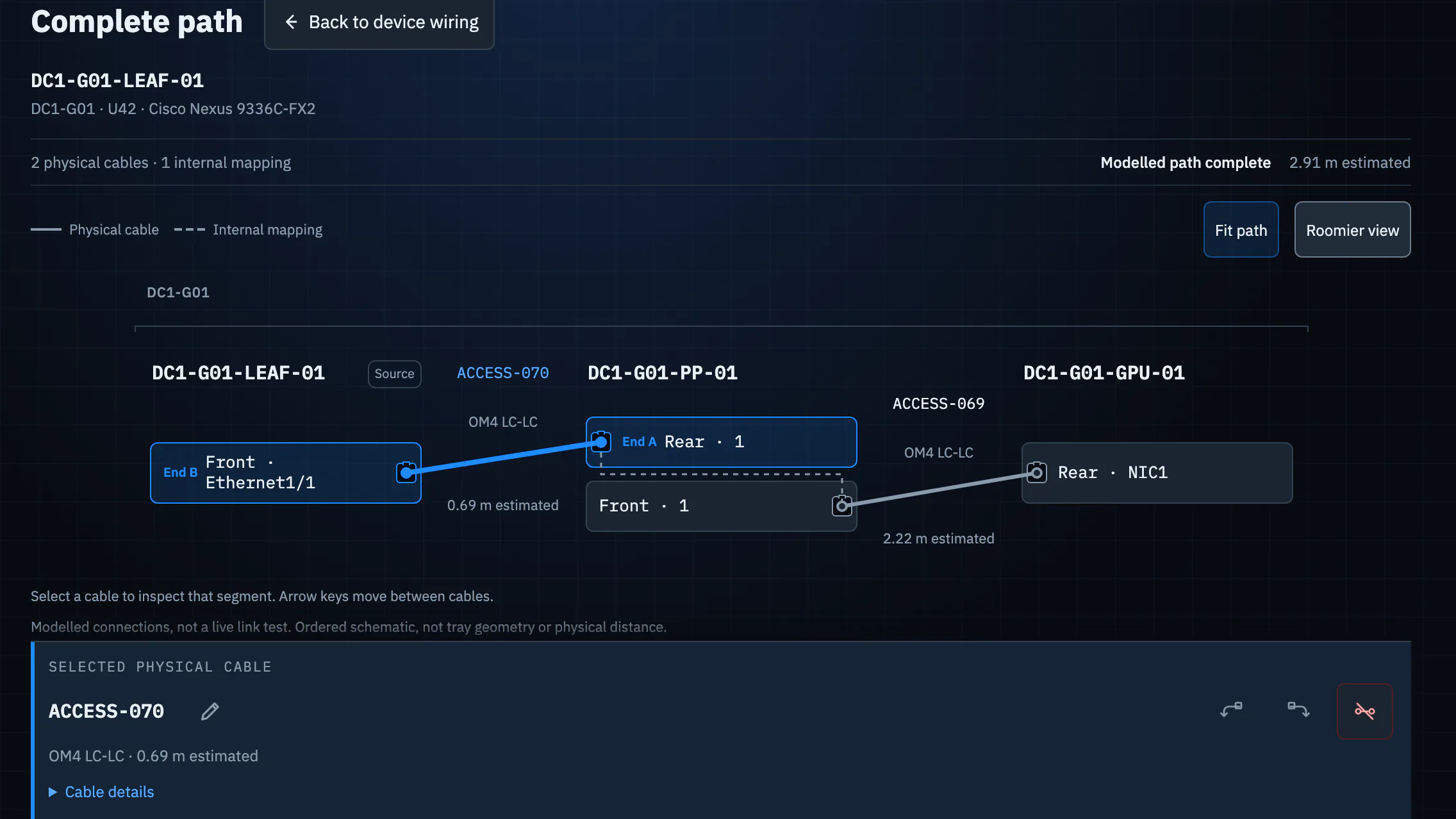
A line between two devices hides the patch field in the middle. Model named ports, physical cables and panel mappings, then inspect the complete path from its source to the far endpoint.
Explore the example first; an account is needed to save your own work.
THE JOB TO DO
A connection is more than its two endpoints
When a link crosses a patch panel, an endpoint-only diagram cannot show which run lands on each panel port or where continuity breaks. A structured record lets the team answer which port a device uses, what lies between the endpoints and which cable to inspect first.
THE WORKFLOW
Trace the path, then prepare the install
Record device wiring
Select a device in Cabling to see its template, module and custom ports. Connected and free ports stay visible, with the direct cable termination and any resolved onward endpoint.
Model the patch field
Connect physical cable ends to named ports and record the patch panel's internal front-to-rear mapping. Railyard can then show a complete path across multiple cables and a panel.
Inspect and export
Open Complete path to follow the ordered segments and spot unresolved ends. Use the cable schedule and label CSVs when preparing the physical installation.
THE RESULT
Give every run a traceable place in the plan
The same record can support a design conversation, an installer schedule and later troubleshooting. The complete-path view distinguishes physical cable runs from an internal panel mapping, so the handoff does not flatten them into one ambiguous link.
SEE IT IN CONTEXT
Start with a real example estate.
Follow one guided task, then inspect how the rack, cables, power and export fit together.